
AMR Steer-Drive & Swerve Gearbox Sizing: Traction vs. Steering Reducer Engineering for Omnidirectional Robots
Size an AMR gearbox for steer-drive robots: compare steering scrub torque, traction loads and reducer layouts. Use the RFQ checklist to request a sizing review.
Size an AMR gearbox for a steer-drive (swerve) module as two coupled load cases: wheel traction and azimuth steering. Traction sizing starts with wheel force, speed, duty cycle, and bearing reactions. Steering sizing starts with tire scrub resistance, rotation time, stiffness, and the load path through the module support bearing. A torque or ratio match alone cannot qualify either axis.
Scope and review date: Reviewed 28 October 2026 for global AMR mechanical engineers, system architects, and procurement teams. SI units are used throughout. This guide covers independently driven and steered industrial wheels on hard floors. The worked example is a hypothetical, reproducible screening calculation, not a measured robot test or a catalog guarantee. It excludes uneven load sharing, detailed tire deformation, thermal validation, and vehicle safety approval; production selection requires measured loads and supplier application sign-off.
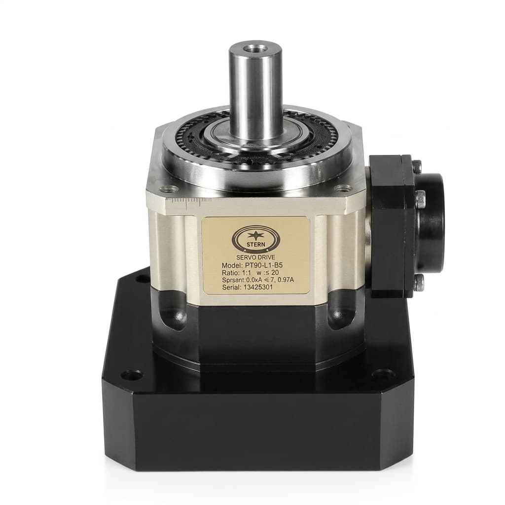
The cover photograph illustrates a gearbox component; it does not identify a qualified steer-drive assembly for the example.
If you are developing an omnidirectional chassis, request a steer-drive engineering review with your wheel load, steering geometry, motion profile, and duty cycle.
1. Why Steer-Drive Modules Demand Two Distinct Gearbox Sizing Philosophies
In conventional differential-drive AMRs, steering is achieved kinematically through velocity differentials across two fixed driven wheels. In contrast, an independent steer-drive (or swerve drive) module actively controls two independent mechanical degrees of freedom per wheel:
- The Horizontal Traction Axis: Converts motor rotational torque into linear thrust along the floor plane. It sustains continuous rolling resistance, high acceleration peaks, ramp gradeability loads, and continuous overhung vertical reactions (
Fr) from vehicle and payload weight. - The Vertical Azimuth Steering Axis: Rotates the traction wheel assembly about the vertical Z-axis, within the module's cable and mechanical limits. It must overcome contact resistance during parked or low-speed steering as well as dynamic torque during motion.
+-----------------------------------------------------------------------------------+
|                        AMR CHASSIS / MOUNTING SUBFRAME                            |
+-----------------------------------------------------------------------------------+
                                         |
                       [Overturning Moment & Axial Thrust]
                                         v
               +----------------------------------------------------+
               |   AZIMUTH STEERING AXIS (Vertical Z-Axis)          |
               |   - Backlash Set by Motion Budget                 |
               |   - Overcoming Static Scrub Torque (T_scrub)       |
               |   - Rigid Slew Bearing / Cross-Roller Support      |
               +----------------------------------------------------+
                                         |
                                         v
               +----------------------------------------------------+
               |   TRACTION PROPULSION AXIS (Horizontal Drive)      |
               |   - Coaxial / Right-Angle Planetary Wheel Hub      |
               |   - Continuous Driving Torque (T_2N)               |
               |   - High Cantilevered Radial Bearing Capacity (Fr) |
               +----------------------------------------------------+
                                         |
                       [Tractive Force & Ground Reaction]
                                         v
                               ====== FLOOR ======
Treating the module as one actuator can hide two important risks. These are mechanisms to investigate, not failure-frequency or lifetime predictions:
- Steering overload: An inertia-only estimate omits contact patch scrub resistance. Under high wheel load, parked steering can exceed the motor current limit or reducer peak torque rating.
- Tracking error: Backlash, elastic twist, encoder placement, tire slip, and controller tuning all affect wheel heading. Reducer backlash alone cannot predict SLAM behavior or docking accuracy.
2. Steer-Drive Kinematics and Force Decomposition
To calculate reducer loads on both axes, define the physical coordinate system, lever arms, and contact patch interactions.
Conceptual load-path illustration, not a dimensioned assembly or evidence of tested load capacity. The steering-axis offset shown does not distinguish longitudinal trail from lateral scrub radius.
3. Azimuth Steering Axis Sizing: The Friction Mechanics of Scrub Torque
Stationary steering can require substantial torque because the contact patch must deform or slide around the steering axis. Rolling steering is a separate load case and should be measured at the commanded speed and wheel load.
3.1 Contact Patch Scrub Mechanics
Let W be contact patch width, Lc contact length, Fz wheel normal force, and mu_s the tire-floor static friction coefficient. With local pressure p(x, y), a Coulomb-friction screening model is:
T_scrub = mu_s * integral_over_patch(p(x, y) * distance_to_steering_axis(x, y) dA)
Fz = integral_over_patch(p(x, y) dA)
This model assumes gross sliding about the steering axis and a constant friction coefficient. It does not capture elastic tire wind-up or partial slip. For a centered rectangular patch, every point lies within half its diagonal, giving a conservative geometric bound within this model:
rho_max = 0.5 * sqrt(W^2 + Lc^2)
T_scrub,center <= mu_s * Fz * rho_max
Use loaded contact dimensions and friction measurements for the actual compound and floor. The example's mu_s = 0.60 is an assumed input, not a universal polyurethane value.
3.2 Steering-Axis Offset and Caster Trail
Define e as the horizontal distance between the steering-axis ground intersection and the contact patch center. Longitudinal trail and lateral scrub radius are different geometries; an arbitrary offset does not guarantee self-centering.
The triangle inequality gives a screening bound for the same friction model:
T_scrub,offset <= mu_s * Fz * (rho_max + abs(e))The additional term mu_s * Fz * abs(e) is a bound, not an independently measured torque to add to an exact tire model. For example, 3,000 N * 0.60 * 0.025 m = 45 N m is an offset allowance; it does not establish the total steering torque. If the wheel rolls while steering, this stationary-slip model may overestimate the resistance.
3.3 Dynamic Steering Torque and Motion Time
T_steer = J_module * alpha_steer + T_contact + T_bearing + T_cableInclude support-bearing and seal drag, cable or slip-ring resistance, and the actual contact load. Project any additional coupling moments onto the steering axis; a spinning wheel's gyroscopic reaction is not automatically an azimuth drive torque.
For a symmetric triangular velocity profile starting and ending at rest:
alpha_steer = 4 * angle / move_time^2
omega_peak = 2 * angle / move_time
A 180-degree move in 0.5 s therefore needs alpha = 50.3 rad/s^2 and omega_peak = 12.57 rad/s (120 rpm). Jerk-limited profiles require their own calculation. Check motor torque at the resulting speed, drive current limits, reducer input-speed limits, and repeated-cycle heating.
3.4 Steering Backlash and Path Tracking Stability
A constant, uncompensated heading error beta produces geometric lateral error delta_y = D * tan(beta). The table converts an assumed angular error into displacement over 10 m. Using a reducer's full backlash as beta is a screening scenario, not a prediction of the actual wheel angle.
| Assumed Constant Heading Error | Geometric Lateral Error over 10 m | How to Use It |
|---|---|---|
| 1 arcmin | 2.9 mm | Compare with the allocated steering error budget |
| 2 arcmin | 5.8 mm | Include bearing and housing deflection separately |
| 3 arcmin | 8.7 mm | Check encoder location and reversal compensation |
| 5 arcmin | 14.5 mm | Verify loaded heading error during direction changes |
| 7 arcmin | 20.4 mm | Evaluate whether closed-loop correction meets the duty |
| 12 arcmin | 34.9 mm | Reassess the motion budget before accepting a reducer |
Allocate backlash, torsional compliance, encoder error, tire slip, and controller error separately. Low backlash does not guarantee low lost motion under load or eliminate navigation hunting. Agree on the test torque, temperature, and wear condition with the supplier.
4. Polyurethane Tread Selection and Steering Sizing Interactions
Wheel compound and tread profile affect the contact patch, rolling resistance, traction, and floor pressure. Shore hardness alone does not determine these properties.
- Softer compounds: May improve compliance and vibration isolation, while increasing deformation and hysteresis. Measure parked steering torque and rolling resistance at the intended wheel load; do not apply a universal scrub-torque multiplier.
- Harder compounds: May reduce deformation, but floor grip, shock transmission, temperature, and compound chemistry still matter. The example uses 95A as a stated scenario input, not a requirement for heavy AMRs.
- Crowned tread: Can reduce effective contact width, but changes contact pressure and load capacity. Ask the wheel supplier to approve the crown geometry, floor pressure, speed, and payload before crediting a steering-torque reduction.
Record the compound, loaded contact patch, temperature, wear state, and floor contamination during testing. A dry-floor result cannot establish wet-floor traction or stopping performance.
5. Traction Propulsion Axis Sizing: Overhung Radial Dynamics
5.1 Rolling Resistance, Acceleration, and Gearbox Output Torque
For equal load sharing on a slope, let m be laden vehicle mass, n the number of driven wheels, theta slope angle, and g = 9.81 m/s^2:
Fz = m * g * cos(theta) / n
F_grade = m * g * sin(theta) / n
F_cont = c_r * Fz + F_grade
F_peak = F_cont + m * a / n
T_out,cont = F_cont * Rw
T_out,peak = F_peak * Rw
T_motor = T_out / (i * eta)
n_wheel = 60 * vehicle_speed / (2 * pi * Rw)
Here c_r is a dimensionless rolling-resistance coefficient and i is the motor-to-output speed ratio. Output torque is the wheel torque; gearbox efficiency belongs in the motor-side calculation. Add wheel and drivetrain rotational inertia, auxiliary drag, unequal load sharing, and the specified service margin when relevant. Check usable traction against the measured tire-floor limit.
5.2 Dynamic Cantilever Radial Load
A direct-mounted wheel sends ground forces and bending moments through the gearbox output support. For an initial combined-force screen:
F_resultant = sqrt(Fz^2 + F_traction^2)
F_screen = k_dyn * F_resultant
M_overhang = force_component * corresponding_lever_arm
k_dyn is an assumed or measured application factor, not a universal floor-joint constant. This resultant is not the equivalent load of either individual bearing. Lateral force, bearing spacing, wheel overhang, and housing stiffness determine bearing reactions.
Use our wheel drive radial and overhung load sizing guide for the load-path worksheet. The SKF bearing rating-life guide is a reference for separating fatigue-life calculations from static and peak-load checks. Specify the duty spectrum, speed, lubrication, and contamination assumptions; a static radial rating cannot prove service life.
Deep-groove, angular-contact, tapered-roller, and externally supported arrangements must each be checked against their actual loads. Bearing type alone does not establish suitability.
6. Comprehensive Reducer Architecture Comparison Matrix
Use this six-row matrix to shortlist architectures. Ratio, efficiency, backlash, stiffness, torque duration, and bearing capacity are model-specific; no generic shock multiplier qualifies an architecture.
| Reducer Architecture | Candidate Axis | Packaging Benefit | Main Sizing Risk | Evidence to Request | Procurement Boundary |
|---|---|---|---|---|---|
| Precision flanged planetary, coaxial | Traction; steering if qualified | Compact coaxial torque path | Output bearing load and reversal error | Load application point, bearing reactions, loaded backlash, torque-speed limits | Confirm wheel overhang and duty before choosing a frame size |
| Right-angle bevel-planetary | Traction | Reorients the motor for constrained envelopes | Extra mesh loss, bearing reactions, and lubrication orientation | Efficiency map, mounting orientations, output-load envelope | Compare the complete motor and fork layout |
| Hollow-shaft strain-wave reducer | Steering | Cable-routing bore and compact axial layout | Torsional compliance, repeated peak torque, and flexspline life | Lost-motion curve, rated/peak torque durations, stiffness and life calculation | Low backlash does not imply unlimited shock capacity |
| Precision cycloidal reducer | Steering | Integrated support options and compact high reduction | Mass, inertia, torque ripple, and bearing moment load | Reversal error, support-bearing ratings, cyclic load approval | Confirm the specific size and configuration |
| Slew-bearing and geared steering module | Steering | Separates turntable support from the drive train | Total pinion/ring backlash and mounting deflection | Combined moment/axial/radial load envelope and measured total lost motion | Include every transmission stage in the accuracy budget |
| Direct-drive torque motor with external support | Steering | Eliminates gear mesh backlash | Low-speed thermal demand, motor diameter, and support stiffness | Continuous stall torque, thermal model, bearing loads, encoder performance | Include drive, cooling, brake, and support costs |
The Harmonic Drive rotary actuator catalogue illustrates hollow-shaft and integrated actuator layouts. It is a supplier product reference, not an AMR steering standard or approval of the worked example. The Neugart NGV application-specific gearbox catalogue is a further wheel-drive reference; obtain current model drawings and load limits before comparison.
After shortlisting an architecture, send the two-axis load cases for a sizing review, including peak duration, repeat rate, and available motor speed.
7. Swerve Drive vs. Mecanum vs. Differential Drive: Application Boundaries
- Differential drive: A useful baseline when lateral translation is unnecessary. Check turning clearance, caster behavior, traction, and docking maneuvers against the actual route.
- Mecanum drive: Provides omnidirectional motion without steering actuators. Validate roller contact loads, floor joints, traction, and vibration with the chosen wheel. Payload alone does not establish a universal exclusion threshold.
- Steer-drive (swerve): Adds independently controlled wheel direction and traction at the cost of steering actuators, cable management, support bearings, and more complex control. It can suit lateral docking and mobile manipulation, provided steering transitions and wheel alignment meet the route requirements.
Compare swept envelope, floor condition, loaded stopping behavior, docking repeatability, energy use, and maintainability. Neither an aisle-width threshold nor a claim of vibration-free motion is enough to select the platform architecture.
8. Integrated Steer-Drive Sizing Example: 1,500 kg Heavy-Duty AMR
This hypothetical example reproduces a screening calculation. All friction, contact geometry, efficiency, and impact inputs below are assumptions. No test, selected product, or fleet lifetime is claimed.
Robot Sizing Parameters
- Laden mass: 1,500 kg; four equally loaded driven modules; level floor; rounded
Fz = 3,680 Nper wheel. - Wheel: 200 mm diameter (
Rw = 0.100 m); assumed 95A polyurethane; rectangular loaded patchW = 0.060 m,Lc = 0.035 m. - Contact inputs:
mu_s = 0.60,c_r = 0.015, steering-axis offset magnitudee = 0.015 m. - Travel target: 1.8 m/s, acceleration 1.0 m/s^2; no grade or unequal load sharing in this example.
- Steering target: 180 degrees in 0.5 s, starting and ending at rest, triangular velocity profile;
J_module = 0.08 kg m^2.
Step 1: Steering Axis Screening Calculation
The centered-patch geometric bound and offset allowance from section 3 give:
rho_max = 0.5 * sqrt(0.060^2 + 0.035^2) = 0.03473 m
T_center,bound = 0.60 * 3,680 * 0.03473 = 76.7 N m
T_offset,allowance = 0.60 * 3,680 * 0.015 = 33.1 N m
T_static,bound = 76.7 + 33.1 = 109.8 N m
alpha = 4 * pi / 0.5^2 = 50.3 rad/s^2
T_inertia = 0.08 * 50.3 = 4.0 N m
T_peak,screen = 109.8 + 4.0 = 113.8 N m
T_spec,screen = 1.35 * 113.8 = 153.7 N m
The factor 1.35 is an example design allowance, not a minimum prescribed by a standard. Bearing, seal, and cable resistance are omitted and must be added before application approval. The static value is a conservative bound within the assumed friction model, not an experimentally established peak.
For an assumed servo peak torque of 4.5 N m and steering transmission efficiency of 0.80:
i_min,torque = 153.7 / (4.5 * 0.80) = 42.7
omega_peak = 2 * pi / 0.5 = 12.57 rad/s = 120 rpm
At candidate i = 50:1, motor_peak_speed = 50 * 120 = 6,000 rpm
A 50:1 candidate passes only the simplified torque arithmetic. It remains unqualified until the motor supplies the required torque at the corresponding speed, the reducer accepts the input speed, and peak duration, life, and thermal checks pass. If 6,000 rpm is unavailable, change the motor, ratio, geometry, or steering-time target. Rated motor torque alone does not settle this conflict.
Step 2: Traction Axis Screening Calculation
F_roll = 3,680 * 0.015 = 55.2 N
F_acc = 1,500 * 1.0 / 4 = 375 N
F_peak = 55.2 + 375 = 430.2 N
T_out,continuous = 55.2 * 0.100 = 5.52 N m
T_out,peak = 430.2 * 0.100 = 43.02 N m
n_wheel = 1.8 * 60 / (pi * 0.200) = 171.9 rpm
At candidate i = 20:1, motor_speed = 3,438 rpm
At assumed eta = 0.94, T_motor,peak = 43.02 / (20 * 0.94) = 2.29 N m
F_screen = 1.8 * sqrt(3,680^2 + 430.2^2) = 6,669 N
The factor 1.8 is an assumed impact screen. The 6.67 kN result is an applied wheel-force screen, not an individual bearing's equivalent dynamic load. Verify lateral force, load application distance, bearing reactions, static capacity, and fatigue life separately. A supplier must also evaluate rotational inertia, braking loads, repeated acceleration, thermal duty, and mounting stiffness before recommending a gearbox.
RFQ decision: Submit the 153.7 N m steering screen and 120 rpm steering peak together, plus the 43.02 N m traction peak at a 171.9 rpm wheel-speed target. These are envelope values; attach the time histories to identify which peaks coincide. Include the omitted loads, required event durations, and target service life before asking the supplier to qualify a reducer.
9. Steer-Drive Engineering & Procurement Checklist
Before comparing quotations, record these inputs and request evidence for the proposed model:
- Separate axis loads: Traction and steering calculations identify continuous, repeated peak, and exceptional braking events.
- Contact test: Wheel load, compound, loaded patch, floor, temperature, and stationary/rolling steering resistance are recorded.
- Offset geometry: Drawings distinguish trail, lateral scrub radius, wheel overhang, and the support-bearing reference plane.
- Heading error budget: Loaded backlash/lost motion, torsional stiffness, encoder placement, temperature, and wear conditions are specified.
- Output support: Radial, axial, and moment loads include the application point, lateral scrub, and a justified impact factor.
- Steering motion: Move angle, start/end speed, acceleration, jerk, peak speed, and motor torque-speed availability are checked together.
- Wheel approval: The wheel supplier confirms load, speed, floor pressure, compound, and crowned tread geometry where used.
- Duty and temperature: Repeated steering, traction, braking, enclosure temperature, lubrication, and cooling assumptions are included.
- Cable and rotation limits: The harness, slip ring, mechanical stops, software limits, and fault response support the required steering range.
- Supplier evidence: Model-specific drawings, torque-duration limits, loaded lost-motion tests, bearing-life assumptions, and inspection records accompany the quotation. Any quality certificate is checked for issuer, scope, and validity; it does not establish drivetrain performance.
10. Frequently Asked Questions (FAQ)
Can we use a planetary gearbox for the azimuth steering axis?
Yes, if its loaded reversal error, stiffness, torque-speed capability, life, and support arrangement meet the application. A separate turntable bearing can isolate support loads from the reducer. Cycloidal and strain-wave reducers are alternatives; payload or architecture name alone cannot qualify or exclude a model.
Why does our steering motor trip on overcurrent when the robot turns from a complete stop?
Stationary tire scrub is one possible cause. Also check bearing preload, cable drag, acceleration commands, motor torque-speed capability, and drive limits. Measure current and steering torque under controlled wheel load. Rolling before steering can reduce scrub in some geometries, but must fit the route and approved motion behavior; increasing ratio also increases the required motor speed.
How does caster offset affect steering stability and motor power?
Longitudinal trail can create a self-aligning moment during rolling; lateral offset is a different lever arm. Both affect contact forces about the steering axis. Specify their direction and magnitude, then compare parked and rolling steering tests. No universal 10–15 mm limit applies to every heavy AMR.
Which failure mechanisms should we check in traction gearbox output supports?
Check bearing fatigue, static indentation, shaft/housing deflection, seal alignment, lubrication, and contamination. A cantilevered wheel can impose a large bending moment, but the governing failure mode depends on the design and duty. Bearing type alone does not prove suitability or establish the root cause of leakage.
When should we choose a right-angle traction gearbox over an in-line coaxial planetary?
Choose by the complete motor, gearbox, wheel, and fork envelope. A right-angle layout changes motor orientation and may help packaging, while adding transmission and lubrication considerations. Compare the candidates' actual efficiency maps, mounting limits, cost, service access, and output support capacity.
How does regenerative braking affect steer-drive gearbox sizing?
Evaluate the commanded and fault-stop deceleration, vehicle mass, wheel radius, module headings, traction limit, and brake arrangement. Regenerative braking is only one possible stopping mode. Check both axes for the resulting back-driving and lateral loads, using the supplier's event torque and duration limits. There is no universal 300% torque allowance, and this guide does not establish compliance with vehicle safety requirements.
11. Sources and Engineering References
These primary supplier references provide component and bearing-selection context. The friction bound, heading-error table, and worked example are explicitly derived here; they are not attributed to a standard or presented as supplier ratings.
- Harmonic Drive LLC — Rotary Actuators. Manufacturer reference for hollow-shaft and integrated rotary actuator layouts. It does not certify a particular actuator for this AMR example. Rotary actuator catalogue.
- SKF — Size selection based on rating life. Bearing-selection reference; use the specific bearing and load spectrum for fatigue calculations and check static loads separately. Bearing rating-life guide.
- Neugart — NGV application-specific gearboxes. Manufacturer catalogue reference for wheel-drive integration. Obtain the current variant drawing, load application point, and approved duty rather than transferring a family-level claim to a selected unit. NGV gearbox catalogue.
12. Engineering Collaboration & Sizing Review
Use the two-axis load cases to compare planetary gearboxes for AMR wheel drives, right-angle gearboxes, cycloidal reducers, and harmonic drives for precision motion axes. Ask for model-specific torque, speed, support-bearing, and lost-motion evidence before approving a candidate.
For a useful application discussion, share laden mass and load distribution, wheel and contact geometry, the steering motion profile, traction speed and grade, floor conditions, and the repeated duty cycle. Include packaging drawings and the desired prototype quantity if available.
Submit your drivetrain specifications for an engineering review to discuss candidate layouts and the evidence needed for selection.
Categories
Need an AMR Gearbox Recommendation?
Reference this article and share your constraints. Our team replies via [email protected].
More Posts
AMR Gearbox Market Update: EU Brake and Cyber Audits
W27 AMR gearbox sourcing update: EU Machinery Regulation 2023/1230 applies Jan 14, 2027, forcing SBC brake evidence and cybersecurity audits for OEMs.

Right-Angle Gearbox Selection for Tight AMR Layouts: Bevel, Worm, and Hypoid Compared
Right-angle gearbox selection for tight AMR layouts. Bevel vs worm vs hypoid comparison with efficiency penalties and decision tree.
AMR Gearbox Market Update 2026-W29: The Shift to Integrated Safety Wheel Drives (IDMs)
W29 AMR gearbox sourcing update: why IDMs, EU 2023/1230, ISO 3691-4, noise, lifetime, and TCO are changing reducer RFQs.