
AMR Wheel Drive Radial & Overhung Load Sizing: Preventing Output Bearing and Gear Failure
Size AMR wheel drive radial and overhung loads using bearing reactions, ISO 281 life and RFQ checks. Compare load cases and request a supplier sizing review.
AMR wheel drive radial and overhung load sizing requires more than a torque rating: determine the load on each wheel, its offset from the gearbox reference plane, the resulting bearing reactions, and the fatigue load spectrum. Check short impact events separately against static and peak limits. A gearbox rated for the required wheel torque may still be unsuitable for carrying vehicle weight directly.
Scope and review date: Reviewed 25 October 2026 for global AMR/AGV mechanical engineers and procurement teams, using SI units. The calculations below are reproducible, hypothetical screening examples, not measured fleet results or product ratings. They cover output support loads and basic bearing fatigue life; they do not approve vehicle safety, gear tooth strength, thermal capacity, seals, or a supplier's complete drivetrain.
If you already have a wheel drawing and duty profile, request a drivetrain sizing review with the load application point marked. Otherwise, use the RFQ checklist in section 9 to prepare those inputs.
1. Why Torque Alone Cannot Qualify an AMR Wheel Drive
A shaft-output gearbox driving a separately supported axle has a different load path from a gearbox with a wheel mounted directly on its output. In the latter arrangement, wheel-ground forces pass through the output bearings, housing, and chassis mounting interface.
Four conditions need separate attention:
- Vehicle weight distribution: payload position, caster preload, and suspension travel change the reaction at each driven wheel.
- Wheel overhang: a wider wheel or spacer moves the contact center farther from the support, increasing bending moment at the same force.
- Floor impacts: joints and thresholds introduce transient loads that depend on speed, tire compliance, wheel diameter, and suspension.
- Turning and braking: lateral tire scrub, traction, and braking add forces and moments that may coincide with the vertical wheel load.
Excessive bearing loading or shaft deflection can contribute to seal leakage, bearing damage, and gear misalignment. Similar symptoms can also arise from lubrication, contamination, assembly, or torque overload; noise or leakage alone cannot identify the root cause. No universal failure-hour threshold applies to all AMR gearboxes.
2. Force Vector Mechanics: Overhung Load and Tilting Moment
Define the coordinate system before comparing a catalog rating with a wheel drawing:
F_z: vertical wheel-ground reaction, perpendicular to the wheel axle.F_t: traction or braking force, also perpendicular to the axle; for wheel torqueT_wand rolling radiusr,F_t = T_w / r.F_r: resultant external radial force; with perpendicular vertical and traction components,F_r = sqrt(F_z² + F_t²).F_a: force parallel to the axle, such as lateral tire scrub during turning.L_w: distance along the axle from the gearbox mounting face to the wheel contact center plane.e: distance from the outer bearing B2 reaction plane to the mounting face, positive outward from B2 in this diagram.a = L_w + e: actual overhang from B2 to the applied radial load;bis the bearing reaction-plane spacing.
Engineering schematic, not to scale. Arrows show forces on the shaft. The mounting face and outer bearing reaction plane are different references; the bearing forces cannot be calculated from flange offset alone.
2.1 Static Radial Load per Drive Wheel
For an assumed symmetric two-wheel load split:
F_z,stat = (M_chassis + M_payload) × g × eta_weight / N_drivenHere masses are in kg, g = 9.81 m/s², eta_weight is the fraction of total weight supported by all driven wheels, and N_driven is their count. Obtain the weight fraction from a chassis equilibrium/suspension model or wheel-load measurements. Do not assume equal wheel loads when the center of gravity, floor, or suspension is asymmetric.
Hypothetical example: a 250 kg chassis, 1,000 kg payload, two driven wheels, and an assumed 70% driven-wheel weight share give:
F_z,stat = (250 + 1,000) × 9.81 × 0.70 / 2 = 4,291.9 N per wheel2.2 Dynamic Shock Load: Separate Assumptions from Measurements
There is no universal floor-condition-to-shock-factor table. Use instrumented wheel loads or a validated vehicle dynamics model for the intended tire, payload, speed, and floor profile. If those data are unavailable, document an agreed screening assumption and keep hardware approval conditional on validation.
For arithmetic only, assume k_dyn = 2.4 and neglect traction in this vertical-load example:
F_r,peak = F_z,stat × k_dyn = 4,291.9 × 2.4 ≈ 10,300 NThis is an assumed short peak, not a continuous fatigue load. Record its duration, frequency, and whether the wheel rotates during the event. Adding the same shock factor again to a measured peak would double-count it.
2.3 Flange Moment and Bearing Reaction Forces
For a tread width of 70 mm and a 25 mm gap from the mounting face to the near tread edge, L_w = 25 + 70/2 = 60 mm. The radial-force moment about that mounting face is:
M_face = F_r × L_w = 10,300 × 0.060 = 618 N·mNow assume B2 is 10 mm inside the mounting face (e = 10 mm) and the reaction-plane spacing is b = 30 mm. For a simple two-support shaft with an external radial force and no other applied bending couple:
a = L_w + e = 60 + 10 = 70 mm
|R2| = F_r × (1 + a/b) = 10,300 × (1 + 70/30) ≈ 34,333 N
|R1| = F_r × a/b       = 10,300 × 70/30          ≈ 24,033 N
B2 acts opposite to the applied radial force; B1 acts in the same direction as that force. Their signed sum balances the external load. These are simplified bearing reaction magnitudes, not allowable loads or proof that damage occurs.
Use the manufacturer's effective reaction planes for angular-contact/tapered arrangements. Preload, gear forces, shaft/housing flexibility, and bearing geometry can change the internal load distribution. Axial force applied at the wheel tread also creates a moment involving the wheel radius; submit the full force/moment load case rather than checking F_a in isolation.
3. Output Bearing Architecture Comparison
Bearing arrangement is a useful shortlist criterion, but bearing type alone does not determine a permissible radial force, moment, robot payload, or service life. The Neugart NGV product documentation illustrates a purpose-built wheel-drive arrangement with preloaded tapered roller bearings and direct chassis mounting; its ratings remain specific to that product and configuration.
| Technical or procurement factor | Deep groove ball bearings | Paired angular contact bearings | Paired tapered roller bearings | Cross-roller output bearing |
|---|---|---|---|---|
| Load path to confirm | Row count and bearing spacing | Back-to-back or face-to-face layout | Effective reaction planes and adjustment | Ring support and mounting stiffness |
| Radial load evidence | Catalog rating at the actual offset | Combined-load envelope for the pair | Combined-load envelope for the pair | Manufacturer radial/axial/moment envelope |
| Axial load evidence | Permissible load in both directions | Contact angle, preload, and direction | Induced thrust and load sharing | Directional load and moment interaction |
| Moment stiffness evidence | Shaft and bearing deflection model | Pair spacing and preload model | Pair spacing and preload model | Ring/bolt support and stiffness curve |
| Shock screening | Static rating and peak reaction | Static rating and preload retention | Static rating and preload retention | Static moment and ring/bolt limits |
| Thermal considerations | Clearance, fits, and lubrication | Preload change with temperature | Preload change with temperature | Preload and mounting distortion |
| Direct wheel mounting decision | Accept only with verified output limits | Accept only with verified output limits | Accept only with verified output limits | Accept only with verified output limits |
| Procurement evidence | Bearing designation and life sheet | Pair specification and life sheet | Pair specification and life sheet | Supplier assembly life/load calculation |
No row implies a universal ranking by efficiency, shock percentage, price, or life. Compare complete assemblies at the same geometry and duty.
4. Radial Load Derating vs. Cantilever Offset
Catalog radial-force ratings have conditions: reference point, speed, service life, load direction, and simultaneous axial/moment loading. Obtain the vendor's offset curve or calculation rather than transferring a generic derating percentage between gearboxes.
The following calculated geometry sensitivity table uses the same assumed F_r = 10,300 N, e = 10 mm, and b = 30 mm from section 2. It shows demand, not allowable load or measured gearbox performance.
Flange-to-wheel offset L_w (mm) | B2-to-wheel arm a (mm) | Moment at mounting face (N·m) | Outer bearing reaction magnitude R2 (kN) |
|---|---|---|---|
| 15 | 25 | 154.5 | 18.88 |
| 30 | 40 | 309.0 | 24.03 |
| 45 | 55 | 463.5 | 29.18 |
| 60 | 70 | 618.0 | 34.33 |
| 75 | 85 | 772.5 | 39.48 |
| 90 | 100 | 927.0 | 44.63 |
Decision: reducing overhang lowers bearing demand without changing wheel torque. A nominal radial rating at the shaft midpoint is insufficient evidence for a wider wheel. Ask the supplier to confirm allowable radial, axial, and moment loads together at your exact wheel geometry.
5. Direct Wheel Mounting vs. an External Bearing-Supported Axle
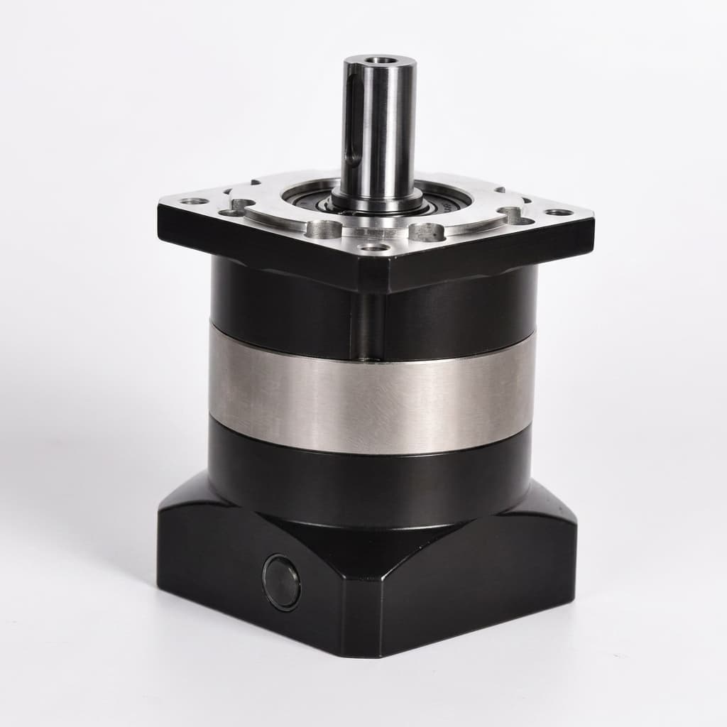
Product illustration: a shaft-output gearbox. The photo does not establish its internal bearing arrangement, radial capacity, or suitability for direct wheel mounting.
Architecture A: Separately Supported Wheel Axle
Mount the wheel on an independent axle supported by chassis bearings, with torque transmitted through a coupling or belt. This can keep the principal vehicle-support loads out of the gearbox output. Coupling forces, belt tension, alignment, and chassis deflection still require calculation.
A single outboard bearing added to an existing rigid gearbox shaft is a different arrangement: it can overconstrain the shaft and redistribute loads unpredictably. Evaluate alignment, bearing fits, and thermal expansion before treating it as an upgrade.
Architecture B: Gearbox with a Rated Wheel-Support Interface
A dedicated wheel-drive assembly carries wheel loads through its rated output support and chassis mount. It can reduce separate axle hardware, but its flange, fasteners, housing, bearing preload, and seals must be checked as a complete assembly.
Compare installed cost using actual quotations, parts, alignment work, service access, and assembly time. Neither architecture has a universal assembly-time or cost advantage. Review our planetary gearbox options and cycloidal reducer options as starting points, then submit the wheel drawing for application review.
6. How Overhung Loads Can Contribute to Bearing and Gear Failure
A possible damage pathway is:
Excessive force or moment
  → shaft/housing deflection or bearing overload
  → changed seal contact or gear alignment
  → contamination, uneven tooth contact, or bearing damage
  → rising vibration, wear, and possible loss of drive
This is a diagnostic hypothesis, not an inevitable sequence. Gear tooth load distribution depends on geometry, stiffness, clearances, and manufacturing tolerances. There is no universal angular-deflection limit or dBA threshold that proves a gearbox is safe or predicts when it will fail.
For a failed unit, retain the wheel geometry, payload and floor-event history, lubrication records, wear photos, and bearing/gear inspection results. Compare observed damage with calculated loads before changing reducer type. The noise testing framework helps define repeatable measurement conditions; it is not a laboratory result for this example.
7. Calculating ISO 281 Basic Bearing Life for AMR Wheel Hubs
The SKF rating-life guidance describes bearing fatigue sizing. Use the bearing maker's load factors and rating definition. SKF also explains why tapered-roller bearing ratings from different conventions cannot simply be compared.
Step 1: Determine Equivalent Dynamic Load at Each Bearing
A common catalog form is P = X × F_r,bearing + Y × F_a,bearing. Select X, Y, and any limiting ratio from the exact bearing/arrangement documentation. Do not use external wheel force as bearing load without first resolving reactions. Include gear loads, preload, and induced thrust where required by the manufacturer's method.
Step 2: Use the Bearing-Specific Life Exponent
L_10  = (C / P)^p                         [million revolutions]
L_10h = 10^6 / (60 × n) × (C / P)^p       [rotating hours]
p = 3 for ball bearings; p = 10/3 for roller bearings
n = 60 × v / (pi × D_wheel)               [r/min, v in m/s, D in m]
C and P must use the same force units and refer to the same bearing or a supplier-defined assembly method. A permissible external wheel load is not the bearing's basic dynamic rating C.
Independent hypothetical arithmetic example: for a roller bearing with C = 38,000 N, an already-resolved constant P = 7,500 N, v = 1.5 m/s, and D = 0.20 m:
n     = 143.24 r/min
L_10  = (38,000 / 7,500)^(10/3) = 223.40 million revolutions
L_10h = 10^6 / (60 × 143.24) × 223.40 ≈ 25,993 rotating hours
Interpretation: basic L_10 is a statistical fatigue-life estimate at 90% reliability for a bearing population under the stated conditions. It is not a warranty, a scheduled failure time, or 90% reliability for the complete gearbox. Lubrication, contamination, installation, and other failure mechanisms can limit actual service life.
Step 3: Combine the Rotating Duty Spectrum and Check Peaks Separately
For a resolved equivalent bearing load P_i in each rotating operating state:
P_eq = [sum(P_i^p × N_i) / sum(N_i)]^(1/p)N_i is the number of revolutions in that state. Time fractions can replace revolution fractions only when speed is the same across states. For varying speed, use the total revolutions over the cycle to convert life to rotating hours. Standstill and shock cases still require static load/deformation and supplier peak-limit checks; do not infer their acceptability from a fatigue-life result.
8. Worked Sizing Example: 1,200 kg Payload Warehouse AMR
This is a hypothetical screening calculation, not a customer case study, hardware test, or approved product selection.
Application Assumptions
- Chassis mass: 280 kg; payload: 1,200 kg; gross mass: 1,480 kg.
- Two driven wheels supporting an assumed 65% of vehicle weight, equally shared.
- Wheel diameter: 200 mm; rotating speed corresponds to 1.5 m/s.
- Mounting-face overhang
L_w = 55 mm; assumede = 10 mm,b = 50 mm. - Vertical-only model: traction, axial scrub, gear loads, and preload are omitted for this arithmetic exercise.
- Assumed peak factor
k_dyn = 2.2; peak load occupies 2% of rotating revolutions and baseline load 98%, both at the same speed. - Requested basic bearing fatigue life: 30,000 rotating hours.
Reproducible Calculation
F_z,stat = 1,480 × 9.81 × 0.65 / 2 = 4,718.61 N
F_r,peak = 4,718.61 × 2.2 = 10,380.94 N
M_face,peak = 10,380.94 × 0.055 = 570.95 N·m
R2 factor = 1 + (55 + 10)/50 = 2.3
P_base = 4,718.61 × 2.3 = 10,852.80 N
P_peak = 10,380.94 × 2.3 = 23,876.17 N
P_eq = [0.98 × P_base^(10/3) + 0.02 × P_peak^(10/3)]^(3/10)
     = 11,623.58 N
L_10,required = 30,000 × 60 × 143.24 / 10^6 ≈ 257.83 million revolutions
C_required = 11,623.58 × 257.83^(3/10) ≈ 61,481 N
The final C_required applies only to the modeled outer roller bearing, with P = |R2| assumed for this purely radial, simplified case. Evaluate B1 and the actual bearing arrangement too. Adding preload, traction, or axial forces can change the required rating.
Procurement Disposition: Conditional Review
Do not select a gearbox solely because a catalog lists a bearing rating above 61.5 kN. Request its actual support geometry, combined-load calculation, life conditions, and static/peak checks. The drawing must also demonstrate that the mounting interface withstands the simultaneous loads. No specific gearbox model is qualified by this example.
The assumed 2% peak share matters: event frequency and severity affect fatigue differently from the single highest shock. Replace both the peak factor and its share with measured or validated data before approval.
Application Decision Matrix
| AMR operating condition | Load uncertainty to resolve | Evidence to request | Selection consequence |
|---|---|---|---|
| Asymmetric pallet loading | Maximum individual wheel reaction | Center-of-gravity envelope and wheel-load model | Size each side for its own worst case |
| Repeated floor joints | Peak magnitude and cycle count | Instrumented force trace at operating speed | Check fatigue spectrum and peak limits |
| Elevator sill crossings | Impact plus possible wheel unloading | Threshold geometry and suspension travel | Validate contact recovery and static load margin |
| Pivot turns | Concurrent axial scrub and moments | Turning load case with contact geometry | Check the combined-load envelope |
| Low-profile chassis | Restricted bearing spacing and large offset | Section drawing with effective support planes | Compare rated hub support with external axle support |
| Washdown or cold storage | Seal/lubricant performance and temperature | Environmental specification and supplier validation | Apply product-specific environmental limits |
9. Engineering and Procurement Checklist for AMR Drive Wheel RFQs
Before releasing an RFQ, agree the following with mechanical engineering and the supplier:
- Wheel geometry: wheel diameter, tread width, spacers, mounting-face offset, and the vendor's load-rating reference plane are marked on the drawing.
- Individual wheel loads: chassis/payload masses, center-of-gravity envelope, caster preload, suspension, and asymmetric conditions are included.
- Dynamic assumptions: floor profile, speed, peak force, event duration, cycle count, and the basis for any shock factor are documented.
- Full force/moment cases: traction, braking, axial scrub, wheel-radius moments, and coincident loading are supplied.
- Output bearing evidence: bearing arrangement, effective support planes, preload method, and relevant dynamic/static ratings are identified or covered by a supplier calculation.
- Fatigue life: the vendor provides bearing-specific
P,C, speed/load spectrum, reliability basis, lubrication assumptions, and requested rotating hours. - Peak and standstill checks: static deformation, housing/flange/fastener strength, and supplier transient limits are checked separately from
L_10h. - Deflection and environment: acceptable output deflection, runout, sealing, temperature, lubricant, and ingress requirements match the actual assembly.
- Qualification evidence: inspection/test conditions cover backlash, preload, noise, and the representative loaded duty; acceptance limits are agreed rather than assumed.
- Commercial handoff: annual quantity, service access, replacement plan, warranty conditions, and spare-module availability are stated.
10. Frequently Asked Questions (FAQ)
Can I reinforce a standard shaft gearbox by adding an external outboard bearing?
Possibly, but an added bearing on the same rigid shaft can overconstrain it. A separately supported wheel axle with a suitable coupling provides a clearer load path. Have the supplier check alignment, thermal expansion, and load sharing before changing the support arrangement.
Why is a catalog radial rating at the shaft midpoint insufficient?
The rating is tied to a stated load application point and life/speed conditions. Moving the wheel outward increases the support moment and bearing reactions. Request the manufacturer's allowable-load curve or application calculation at your exact offset; there is no universal offset correction constant.
Does a harder polyurethane tire imply a fixed shock multiplier?
No. Tire compound, geometry, temperature, wheel diameter, speed, floor profile, and suspension all influence the transient force. Shore hardness alone cannot determine a shock multiplier or energy-transmission percentage. Measure or validate the complete wheel and chassis configuration.
Is a cycloidal reducer always better than a planetary gearbox for radial load?
No. Gear reduction type and output bearing support are separate design choices. Compare complete products at the same radial, axial, moment, offset, speed, and life conditions. Neither gear type alone establishes wheel-load capacity.
What is the maximum permissible output shaft angular deflection?
Use the gearbox manufacturer's assembly-specific limit under your combined load case. Gear geometry, bearing support, seals, and encoder interfaces have different tolerances. A generic arcminute limit cannot approve all precision reducers.
How does pivot turning create axial thrust?
Tire scrub can generate a lateral force parallel to the wheel axle. Because that force acts at the contact patch, it can also create a tilting moment about the output support. Provide the wheel radius and simultaneous radial/traction loads when requesting the supplier's combined-load assessment.
Can I use the largest shock force directly in the bearing-life formula?
A constant peak-load calculation can be a conservative screen, but it does not represent a measured operating spectrum. Use revolution-weighted equivalent bearing loads for fatigue, then check maximum and standstill loads separately. A long calculated fatigue life does not prove impact resistance.
Which grease and seal material should procurement mandate?
Ask the supplier to qualify lubricant and seals for operating temperature, speed, contamination, washdown, compatibility, and permissible shaft motion. Neither FKM seals nor a particular NLGI grease grade is universally required. An assembly's ingress rating must be supported by its actual design and validation.
Sources / References
These sources support bearing-life principles and an example of a dedicated wheel-drive layout. They do not validate this article's hypothetical shock factors, dimensions, duty fractions, or an AMRGearbox product rating.
- SKF — Size selection based on rating life. Manufacturer guidance for bearing fatigue sizing and operating-condition considerations. The page uses a JavaScript shell; consult the current bearing documentation for the full selection method. SKF rating-life guidance.
- SKF Evolution — Tapered roller bearing load ratings versus performance. Explains ISO 281 basic rating life, its 90% reliability basis, and differences between rating conventions. SKF bearing load-rating explanation.
- Neugart — NGV application-specific planetary gearbox. Product documentation showing a preloaded tapered-roller output support and direct chassis/wheel integration. Its configuration-specific ratings must not be generalized to other gearboxes. Neugart NGV documentation.
Request Drivetrain Sizing and RFQ Support
Send your wheel drawing with the offset marked, chassis and payload masses, expected wheel loads, floor-event profile, speed/duty spectrum, target life, and annual quantity to AMRGearbox's inquiry team. Ask for an application-specific load review and quotation, including any missing validation inputs.
Use the gearbox efficiency comparison alongside this load review when assessing battery-runtime trade-offs. Final selection requires the proposed model's documented combined-load limits and your vehicle qualification results.
Categories
Need an AMR Gearbox Recommendation?
Reference this article and share your constraints. Our team replies via [email protected].
More Posts
AMR Gearbox Market Update (2026-W21): New Cost-Transfer Signals, Standards Progress, and the Sourcing Decisions to Lock Before June
Weekly AMR gearbox market update for U.S., EU, and APAC buyers: new duty, standards, and cost-transfer signals, plus sourcing actions to lock before June.

AMR Gearbox Market Update (2026-W25): The July 24 Section 122 Clock Now Sets Reducer RFQ and Landed-Cost Strategy
AMR gearbox market update: the July 24 Section 122 clock, May 7 CIT ruling, and ISO/DIS 25268 reshape reducer landed cost and healthcare-AMR sourcing.
Compact Gearbox Selection for Sub-300mm AMR Chassis
Packaging-first compact gearbox selection for sub-300mm AMR chassis. Stack-up analysis, thermal derating, and integration checklist.